Saturday was a solder-thon day
A previously mentioned, I have purchased pre-assembled Z80-MBC3 and RC2014 electronics boards and components, waiting for "that" rainy day to come along....

Well, yesterday was that day, and boy did it rain! Today, however, lovely sunshine and blue skies. It's early and I'm killing time until I can go and pick up my Jaguar STR, after she's had some bodywork repairs done by an expert/professional. Don't know what one of those is? click here. very rare actually, they only made 129 in the '07 year and there is probably about 30 left on the road. As the paperwork says, "it was the fastest production road car when it was released. faster than any supercars out there...", food for thought, huh? anyway, side-tracked.
So, I have a couple of Z80 CPU based computers I'm going to build - except, they are new, but they are old, retro-vintage, if you like. What's a Z80, you ask? (then you must be <40yrs old), here you go:


As mentioned, I purchased a Z80-MBC3 direct from the guy who invented it, in the Netherlands I believe - here is the WEBSITE. It is a nice & simple basic Z80 processor board that allows you to plug in arduino components to extend it, such as sd-card reader, rtc (real time clock) - something that you don't think you need, until you do!, a serial-to-usb connector to allow plugging into a laptop and using a VT100 (minicom / screen) terminal as well as a bunch of digital and analog GPIO pins that you can access. Basically a Raspberry Pi from the 1980's.

Due to the nice way the board has been designed, the soldering is nice and straight forward, all the components are old skool through holes soldering and not surface mount fiddly stuff, so it is pretty simple to organise soldering the socket casings for the chips, then the larger components and not like me who soldered the pot. first that then made turning the board upside down and balancing it more tricky to solder the other components, kept it "fun" though.
Anyway, after a short while (I had a training course video for "neuro-symbolic AI" on in the background for the whole day), the board was completed and I slotted in the pre-baked sd-card and booted up.


To my surprise, the lights came on and all looked good. As you can see above, on first boot you get the choice of which OS you wish to use on subsequent boots. However, before doing that - set the RTC date/time! select [9] and change the date and time and then reset. If you then select to boot to BASIC and then later want to change this to be CP/M instead, you can get the state of the device back to the above by holding down the [USER] key, wait for blue (or green if you soldered that one instead) led to come on and then press the [RESET] key, the device will restart and you'll be back at the above screen.
It is actually really simple and easy to use, you just have to remember pre-MS-DOS days, or look up the CP/M commands, they're not too dissimilar, after-all it is one of the many things Microsoft copied.
As to using minicom, that's a little quirky. When you start it, start it initially with:
$ minicom -s
select the serial protocol, press [A] and change from /dev/modem to /dev/ttyUSB0, [ESC], save as dfl, then Exit. then you'll drop into the above screen, if you don't see the Z80-MBC3 wording above, just press [RESET] key and it'll then appear and off you go.
The software for everything is open-source and available on github HERE - that is also a useful place to check to see if there has been any firmware updates too.
Naturally, AFTER I'd built it, I found the official YouTube video that gives you a walk through:
As I already have a VGA, PS-2 keyboard/mouse connector board I found this WEBPAGE where someone hooked it up to the device (previous version, but should still work), looks just like a simple switching around for the Tx, Rx connectors and some simple comms. so maybe I'll hook this up soon... and then it'll be a standalone computer being able to plug directly into a monitor and not needing the laptop in the middle? we'll see.
I then caught an "action-shot", note the blue led is on, just missed the yellow led (indicating sd-card activity), the red led is just showing power for the RTC.


What I was trying to show, maybe I should have just video'd it?! d'oh! was the speed of the $ dir command, switching between the 16-drives (I believe it's formatted up to the P: drive) and listing the files, anyway, static images is all you've got. Build one yourself and be amazed.
There is a follow up question later on: "so, what can you actually now DO with it?".
(me: probably put it on the shelf & forget about it for another 6 months until the weather is bad again!")
Here's a short video of running "Hello World" on the device:
.....
INTERLUDE: Want to see what's UNDER my desk?

and what's ON TOP of my desk?

"As above, So below" - yes, those are "old" books that I've been working through over the past decade and more (gosh, some of those are 20+yrs old to me), basically, you can see that I've been wanting/waiting to build a "proper" AI brain. AI software isn't there, yet...although it might be getting closer in the next 4-5 years (btw - don't insult me and tell me about xxxxGPT - I'll send you to the corner of the room and make you wear a pointy-hat!) Hopefully, the AI software & techniques will evolve, hence watching / learning about "neuro-symbolic AI" in the background whilst doing this soldering - and hopefully you won't need a super-computer with a gazillion GPUs on it to make it run - I'm hoping that a Blade Runner style usage of Z80 CPUs will be all that we will need...... lol
INTERLUDE: over
.....
Moving on, whilst I was in full "soldering-mode", I then soldered a Amstrad CPC PIO related expansion connector board and the 2nd PIO board - and again, that worked first time.

......
I couldn't rest there... now I was on video 5 of the "neuro-symbolic AI" videos and I was on a roll.
Bring on the RC2014. Now, this I 100% confess I bought pre-soldered from a chap on eBay as he had already built a couple and didn't need the excess (blimey, selling off your duplicates, shocking...maybe I should start doing that?...maybe....). So I already had a 3-slot backplane board with the Z80 CPU, a CF-Card reader and a serial connection board all ready available and working.
However, as I am me and I cannot, not fiddle around, I wanted to EXPAND beyond what I already had... so I purchased from this WEBSITE an 8-slot backplane board, an ESP8266 Wifi Module and a Pi Pico VGA Serial Terminal. That might have raised an eye-brow or two?!
The above 3 items all came in pre-assembled mode, ie. I need to solder them all! I didn't get a photo of the 8-slot backplane board, but needless to say, it was simple enough, the website is a great resource to help, here it is after I had swapped onto the newly soldered 8-slot backplane board:

Again, shockingly, it worked first time.... I'm getting cocky with my soldering skills about now - that'll come back to bite me later no doubt.

Hmmm.... those existing boards might need to move around a bit to give a bit more space for the new boards, don't want anything getting too close...

...and after actually a not so nice experience of soldering the Wifi module, it's in place:

The Wifi module board itself isn't difficult at all, very few components, however, there is a surface mount component, might be related to the 5v down to 3.3v piece (will need to check the schematics on the website) and the 8266 WiFi board itself, well, you cannot solder normal legs into the holes or onto the board, as I was expecting, so that became a very fiddly exercise of taping down the 8266 board, using a pair of tweezers, holding the soldering iron and attempting to put the solder onto the 8266 board and bridge the solder onto the board. I "think" I did it okay...
It all looks good...however, I don't get any indication that the board is working at all. Do I now ave to use an external 5v PSU on the 8-slot backplane board as I'm now demanding more power than the USB through the terminal connector can provide? Are my soldering joints naff? Do I need to get out the beepy prodder thingy to let me trace voltages throughout the board (is this the point I convince myself I need to purchase an oscilloscope?)
The good thing is, the website mentioned above does provide a lot of info / schematics so I can diagnose things pretty easily. For instance, it does tell me the 826 WiFi should already have pre-installed firmware and it should be broadcasting as an AP (access-point) which I can connect to and just use http://192.168.4.1 to get access to the admin console - however, I don't see a new AP appearing when I do a scan....time to check those solder joints. I knew I was getting too cocky :-)
Troubleshooting will now commence. I have an hour before needing to go pick-up Jaguar STR, it is still sunny-ish, fingers-crossed I get it figured out.....
UPDATE:
picked up Jag, they did a good job, might need a bit of a re-buff as colour is a little light, but let's let it settle for a week or so and then they can give it a go again.
After a little bit of gardening (under orders of Mrs.isaGeek) in-between the sun/rain showers, I had a little break and got back to the ESP 8266 Wifi board.
I decided to isolate the board and plug it into the 3-slot backplane board with an external 6v (4x1.5v batteries), I did a little bit of voltage checking and I noticed all was not good. I was tracing the GND and VCC voltages according to the schematic diagram and wasn't getting any voltages....hmmm
right, time for the big guns.... otherwise known as the magnifying glass and my close-up reading glasses! Shhhhh! don't tell anyone I've got them, they indicate I'm getting old (yes, I said "getting" and not "already", I'm not ready to accept it yet)

I gave the 8366 module connections a re-going over with the soldering iron and solder (twice) and then plugged the board in.
Before I turned it on, I thought I would check to see what APs were being picked up:

I then flicked the [ON] switch for the board and I noticed the 8266 blue LED flicked really quickly, now, that indicates to me that it is getting power - I probed the voltages for the pins and it all looked good! In theory it should be working.

I did have to "borrow" a jumper from another piece of hardware (I swear I have an entire box of these somewhere?!!) to close the [enable link] pins to the left of the 8266 module.
There is no real indication that anything is happening / on / working with the board (do the red / green leds flash? I didn't notice - ah, did I do my infamous solder them around the wrong way again? Now, I know I "do" have a box of those, so plenty of spares to re-solder new one's if needed)
So, again, a quick Wifi scan:

SUCCESS! There is the ESP_xxxxx that I was looking for! yay!
Now, what was that IP address? 192.168.4.1 :
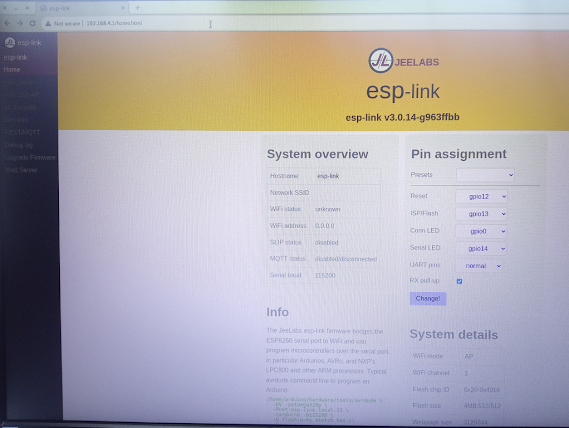
A quick switch from the 3-slot backplane to the 8-slot one, along with the other devices, plugged in and there it is - broadcasting away and accessible.
Superb news! right, that amusingly enough means that I now have a 1970s/80s Z80 CPU connected to a WiFi network, well, I can change the AP to connect to my home network and then I can still [minicom] into it instead of needing the USB cable - and if I can do that, I can then send traffic back and forth over the WiFi network to/from the device. Oh, look there is a REST/MQTT configuration setup too.....
Oh, this needs a whole new weekend to work out what to do with this :-)
UPDATE UPDATE:
okay, so I removed the red/green LEDs (foolishly) and swapped them for blue & yellow - it turns out in the esp-link UI you change the settings and the LEDs show you the traffic (makes sense now)

I had a very nice email follow up from Spencer (the RC2014 website owner) who pointed out that I may have mis-interpreted what the WiFi card is used for. He may have been right. I think I went on a wander-off journey at the weekend and started at the right place and went off on a tangent, thankfully he put me back on track.
I still need to have the Serial board in place! All the WiFi board is doing is removing the need to have the FTDI cable connected between the serial board and the laptop. D'oh!, yes, now it is pointed out, it makes sense.
However, doing that and then checking the esp-link console window I still see garbage output:

I can confirm though, if I don't use this and just use the serial board and FTDI usb cable and minicom I do get the proper text output along with the ability to select CP/M and I can navigate through the drives and run software, so I know it does work.
Let me go check the telnet output....

Ah bugger! hmmm.... okay, so I wonder if it is something to do with the switch setup / config on the serial board? I still have it set as pin 1 = OFF and the rest = ON, which is the default setting.
Hmmmm...more debugging needed, I think.
Okay, so after a brain-wave, I hooked up the WiFi board into the 3-slot backplane on it's own, with power... I then put the serial board back with the CF-card and Z80 board on the 8-slot backplane. I powered them from 5v adapter.
Now, I took a connector from the Rx and Tx from the output of the serial board connections and connected them to the pins on the 3-slot board into the Rx an Tx pin slots next to the WiFi board.
Now...switching everything on.. doing a telnet and I get nothing....
oh hang on, got this before... I preset [reset] button on the 8-slot backplane board and that starts up the Z80 CPU....

Ah, ha! okay, so THAT is what I was expecting to see (sort of). That is the starter for the monitor application.
Oh hang on though, if I type something, it just echo's the output to the telnet session is doesn't actually execute the command to the Z80 - darn it... I should take the win that it is not sending gibberish characters anymore and a quick test via the esp-link console - just to double check. yep, behaves the same:

Soooooooooo close...... but it does prove my theory that having the board plugged into the same backplane is causing conflict of some sort, which is odd, and shall be investigated later - but for now, by splitting this out, I'm starting to get closer to what I was expecting it to do.
(why does it have to be a work day tomorrow?! :-) )
....more updates to come


Comments
Post a Comment