LoRa LoRa LoRa
...and that is not THIS type of Lorra Lorra laughs : Cyla Black
although, my laughs were more tears of woe and then tears of joy-ish
What is LoRa and why is it spelt that way? well, you could DuckDuckGo and search for it, however, simple description: "Lo-ng Ra-nge comms" .
[UPDATE: okay, I'll answer the question, "why bother? why not just use WiFi?" - that is such a non-Gen X question. Right. WiFi sucks a LOT of power, I mean a LOT. It also requires an AP (access point), one device will have to be a gateway router for one device to connect to the other... and also, well, the "LoRa" name says it all... can you move your laptop outside your house, walk down the street, keep walking, keep walking some more and still get a signal to that WiFi AP? no. no you cannot. Ah, ha, then you'll attempt to be smart and say, "4G" or "5G", well, yes, but that needs another device, such as your phone to be required, then you have to connect your device to the phone (burning through 2 lots of battery power sources), what if you just want to have a tracking device connected to, let's say your trailer that sits on your driveway for 9 months of the year. you don't want it to be on all the time do you? no. so upon movement detection you want a mercury switch to turn on the device, then transmit to your home device to let you know that the trailer is moving. This device can sit in minimal usage for years and years, without requiring charging or if you're smart you can have a solar charger somewhere in the equation so it never needs maintenance. However, the usage is to be notified - it's not about streaming Tik-Tok or YouTube videos, that's what your phone is for, this is for sending small but very important pieces of data from one device to another over quite long range distances that are just not possible via WiFi or BLE.]


As is usual, there is a lot of information on the internet and then there is a lack of information on the internet - huh? what do I mean? Well, I purchase 1 of the OLED screen devices and I purchased the same thing without the OLED screen - thinking that I would save a few quid.
My thinking was: I would put this first board onto the RPi4 that has just arrived as that OS will be nice and clean and it should just work straight away. In fact, that is indeed what happened. Pretty awesome really.


First woes were the fact that (and I am ashamed to admit it took a lot longer than it should have done) one of the Arduino UNO R4 devices was kerput, DOA, dead on arrival. Well, if it were dead dead, that would have been easy - however as they put the default blink app on the device, you're lulled into a false sense of "everything is fine". I actually ordered 2 Arduino UNO R4 devices - as yes, you guessed it, I've had similar experience in the past - however, I naturally assumed I was the problem and not the hardware.
I plugged in the arduino device to my personal honor laptop (Ubuntu 22.04) and what I should have done is run "sudo dmesg" at this point as I would have seen that the laptop was having problems with the device hardware, ie. recognising it as a USB or even a serial device. I foolishly assumed that it was obviously the library files within the Arduino IDE, so I blitzed the Arduino IDE 1.5 / 1.8 versions that I had, I installed the new Arduino v2 IDE - went through the teething problems with getting that all up & running and using the Radiohead lora library - only to end up wasting about 6hours and being no further ahead.
I then thought, I have another device, let me try that... ah, that worked straight away. Picked it up in the IDE, let me access the port and even allowed me to upload a new sketch.
Unplugged, plugged in the first device, attempted the same. no dice. hmmmm...
Swapped back over. I can upload a new sketch and I can interface with the RFM95W device (that lacks any form of indication that it is working, maybe a small LED would have been nice to at least tell you it is ON and maybe a Tx/Rx LED to show that traffic is going in/out - appreciate that would eat some battery power, but make it turn on/off-able? anyway)
I used the PIN layout as suggested and the Arduino code as suggested... and it does nothing.
Hmmm.... that's when the good old internet got in my way. I searched high and low for a simple Arduino LoRa library that I could use for 915MHz and I got a variety of flavours, except nothing seemed to work with transmit / receive from the RPi LoRa device.
I went and watched Guardians of the Galaxy 3 movie.
The next day, I thought, hmmm, how about if I use an RPi Pico instead? Well, kiss good bye to another couple of hours. Similar scenario - I built some code just to do the basics, load the LoRa library and device and test being a transmit or receive. No dice.

(yes, it took a double-look for me to realise that the pins were laid at inversely on that vga-board that I was using - I'll come back to trying this again later)

However, in my frustration, I pinged thepihut to ask about a refund for the Arduino UNO R4 - normally, I wouldn't care, I'd just bin it, but these are £28-ish each, so not cheap and cheerful anymore. Whilst I was there, I ordered another Adafruit LoRa Radio Bonnet with OLED - RFM95W for plugging into the RPi 3+ (when it arrives).
I ended up going around in circles with web articles, but settled on this page
https://learn.adafruit.com/lora-and-lorawan-radio-for-raspberry-pi/raspberry-pi-wiring
which has a reliance to install this library:
https://github.com/adafruit/Adafruit_CircuitPython_RFM9x
Which is all good and all - for the RPi, but will not assist me with the Arduino or Pico that I really want to run this on - I'll get back to them later.


Well... also, that other board I ordered will be arriving in a few days, I think I'll end up just connecting that up to the RPi 3+ board as-is and then move the small blue board over to the Pico or Arduino - that way I can experiment with 3-way comms.
I also want to see if I can NOT use CircuitPython? Can I do this natively? Can I do this and have it working from Pico C-code or from Arduino C-code.... there in lies the "simple" challenge. The fact I've got this far along the journey, I'm pretty sure the rest will be smooth sailing..... LOL...
UPDATE:
Well....I got bored watching WOLF .... so I decided to get the Arduino UNO R4 and the second board setup after I found this website:
https://www.electronics-lab.com/project/introduction-lora-send-data-two-arduino-using-lora/
I setup the wiring as per the original connections and as shown below:
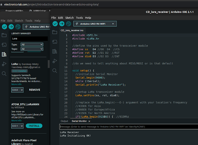
I had to download the [LoRa] library v0.8.0 and then used the code from the above website to test the Receiver code. As you can see the Serial Monitor outputs that all looking good.
I shall now test to see if I can receive a message from the first board........
HA!

Well, would you take a look at that! Okay, I need to clean up the code or the debug output - but it does look like we have a winner! I have the Arduino UNO R4 connected up and doing some receiving!
Maybe later in the week, I'll hook it up to a breadboard, some buttons and can then do some back and forth. Awesome, looks like I got the right LoRa library and can use Arduino C-code without having to use CircuitPython etc... sweet.
(Hmmm....I wonder if I could do something using Node-Red too.... hmmmm....)
Here's the receiver code from above:
UPDATE:
I did modify the code above to listen for a specific message and then return a transmission message back - except in my haste I seemed to have not saved the code. simple enough to redo.
I received the "other" LoRa board with the OLED and plugged it into the RPi3+ device, got it setup in less than 5mins with same code and had it sending/receiving with the LoRa node module - just amusing that as the device already has an OLED screen for outputting networking info, the same info is output onto both screens - will have to change that, but for now, it's good to see it works and the button pressing does the job:


Comments
Post a Comment