ESP8266-01 : smart plug DIY part1
As mentioned in a previous post, I wanted an off-grid smart plug in the UK that did not connect out to the external internet, did not connect up to some AWS service in Germany (and other locations), just for me to be able to turn a switch ON and OFF again. It still baffles me.

(a bit like the sheeple-mindset of fitting a "smart meter" in your house - there is ABSOLUTELY no need or value for doing this - it is purely for the electricity companies to gain full control of your environment, there is zer0 benefit to you... you don't know or even care what a KwH value means, or whether it costs 30p to boil your kettle over a day, you're not going to stop doing it, you just now have too much information - however, at the flip of a remote switch, your electricity provider has the power to switch your tariff, restrict the input/feed of the amount of power you have, switch you from a monthly payment over to a pay-as-you-go and I'm sure all sorts more - you have sleep-walked into handing over control of your essential item to a remote person; well, it'll probably be a pi$$ poor ML algorithm that'll be doing the work, not a human; previously the gas / electricity company had to request permission from the home owner to gain entry to the property in order to make changes to your meter, now they don't need that...and all because they used the guise of Einstein to do it... stop and think about it for a fw minutes, what TRUE benefit do YOU get from the smart meter... and what POWER do the companies get... yeah, very 10/90 equation there, isn't it.... anyway, that was a side-rant from a grumpy old man who should be out in the middle of Glastonbury high-street shouting at the pigeons and taking about "them" :-) disclaimer: yes, I do have one / did have one, it worked okay for about 3-month then stopped working, 2 electricity companies later and they don't seem phased to come and replace it and I've not bothered with it, I just do old fashioned manual meter readings once a month, upload the value and get charged that exact amount)

Back to smart plugs - so I purchased a few of these ESP8266-01 devices, they arrived very quickly and I was chomping at the bit to set them up.

However, I hadn't thought about "how" to set them up - I suppose I was assuming they would be like the Arduino or Raspberry Pi, just plug and plug. Hmmmm.... not so.
I confess, I did a fair amount of DuckDuckGo-ing on this one and I found a LOT of mi-sinformation, or out of date information (2012 / 2015 / 2018) and as they say YMMV (You Mileage May Vary - a hell of a lot!) There were a lot of crazy suggestions, that were very complex, a lot of over-simplified suggestions, that were just repeats of other peoples postings, that would never work, could never work - but lazy internet people just copy&pasted to get traffic to their website / YouTube video... it goes on.
First of all, I was very chuffed with myself for FINALLY getting my work / work T50 ThinkPad laptop (running Red-Hat Linux) to work with an external HDMI AOC screen!!!! you have no idea how much that has been bugging me... turned out I needed to do a BIOS change: Config>Display Discrete Graphics and get the yum update to latest OS libraries... yes, I made it sound so simple there, but it was not...

.....and why was I so happy? well, I run the laptop as-is, over there in the top-middle... it has work / work stuff on it, of course it is locked down / restricted, for very valid reasons.
However, you get [Virtual Machine Manager] installed by default...and well, you can install and run an approved secure version of Ubuntu linux within a VM....that you fully own / control.. and I have set it up to boot the VM on boot up of the laptop and now it boots to full screen on the big monitor (on the right) and that is where I do a vast majority of my play / work... it's my full development / lab. environment - as it's a VM, I snapshot regularly and if I totally knacker the linux OS environment, I can simply rollback - and I have not knackered my original outer shell Red Hat work / work OS laptop. neat huh.
anyway, as they say, "the Lord giveth and the Lord taketh away".... 'cos he's a mean SoB, which I always thought was interesting (different discussion for a different time), when plugging a USB device into the laptop, you have to allow the mapping over into the VMWare image and well, that is software and as we know, software sometimes has bugs and doesn't behave as expected in relation to timings etc.. so there are glitches every now & then.
As I say, I researched a LOT of content attempting to figure out how to program this device. Of course, it is not simple... it wouldn't be, would it. (caveat: I later found a tool you can buy to help program these - see later*)
It turns out that you cannot just plug it in, connect it up to the Arduino IDE and push the program out to it. Which is pretty much what you do with any other Arduino device.
There are a couple of options available, and thanks to a (quite right) Amazon warehouse workers strike over Black Friday, I couldn't just order a next day delivery of a device and get up and running - necessity is the mother of all invention, isn't it... or something like that. So, I had to get a little creative.
Now, a lot of the websites show the usage of an Arduino UNO as a pass-through device. Basically, you connect the Arduino to your laptop. You connect the Arduino IDE to the Arduino - you push out a copy of the "Blink" app to it - the exact app, doesn't matter. Just think of it as a consciousness, you are push out the top layer of thought to the device, you push out the conscious layer, it will now blink forever more, thinking of nothing else....
However, once you have done that, you then connect the Tx and Rx (pins 0 &1 on the Arduino board) to the ESP8266-01 device and the appropriate other cables to GND, 3.3v etc... and then within the Arduino IDE, you switch to the ESP8266 board (under Tools) and then you load the "blink" code for the ESP8266 device and then you press "DEPLOY" or Run or [Compile and then Upload] and this then compiles the code (using avrdude - which you can actually run from the command-line, so no need for the IDE) and then UPLOADs the code to the Arduino UNO... and because you have the Rx/Tx connectors connected, it pushes the data through the UNO and over to the ESP8266-01 device.... so, think of this as pushing the data to the UNOs sub-conscious, you are bypassing the "blinking" LED that is flashing away merrily on the UNO, and you are connecting to the raw IO of the UNO that yo uhave connected the ESP8266 device to, that data is then picked up by the ESP8266-01 device and the "blink" app is uploaded.... well, in theory.
This is what I first got when I tried that:

hmmmm...not quite what I was expecting.... also I was forever getting Timeout issues with the upload.


Now....you lil'b-stard, will you play ball?


Looks like the 10year old board I bought from Sparkfun and never used was just sitting and waiting for it's time to shine! THANK YOU little board of greatness.
Now, as it says, you need to do a reset on the ESP8266-01, basically remove the GND cable like this:

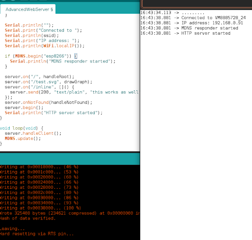
Then start up the [Serial Monitor] on the Arduino IDE....


FINALLY! Well, that was quite some journey.
As I'm a pessimist (at best), I repeated the exercise with ESP8266-01 device number 2 and I got the same result. Sweet, repeatable success - I like it.
Now, to upload something a little more useful - to test the WiFi works:


awesome!
Right, where was that code where I set it up to be a web-server and I pass it some JSON to turn the RELAY ON and OFF via some external system
I also had another doubt at this point - will the RELAY work on 240v mains? That would just be my luck, wouldn't it!....
PHEW, yes.. they handle 10A 250v AC as input and 10A 30v DC as input - I should be good.
Oh and "No", I could not get the "AT" commands to work from the [Serial Monitor], will keep trying, but seeing as I'm doing what I want from code, it doesn't really make much difference.
UPDATE:
and of course this happens.....
I find a more modern FT232R board that allows me to plug directly into the laptop, removing the need for the cable

UPDATE UPDATE:
and then, well, of bl00dy course:


ha...okay, so I found out why there is reference to the ASync Web Server github repo. and it is because I left the web-page for a few minutes and the backend web server became unresponsive; so whilst it works when the client is connected and being used; as soon as it falls asleep, it's dead. you cannot revive from the client side. you need to perform a device reset, that's not good!
and here is the auto-refreshed output:

as you can see, it has been running for 3 1/2 minutes and still responding okay. It refreshes every 10 seconds and produces a different graph output. okay, this should be enough of the skeleton to build upon... we'll see... 5 1/2 mins now...

and whilst I was modifying the code, it did reach 11 mins and still no issues.

what was I adding to the code? just some test / debugs to make sure that the calls work okay:

and in action:


okay, time to port the previous code over and merge here....maybe tomorrow.


Comments
Post a Comment