Solar powered pond - part 3
For once it seems that the planets are aligning - things are slowly but surely actually working out!

I went through the setup of the solar panels with the connectors that I had and as I eluded to previously (and the eagle eyed may have noticed) whilst it was all setup and working things felt about 95% correct and the final 5% was niggling me....
I had setup the solar panels - all 3 of them, yes, I know odd number, I'll be ordering another one, just to make it more fun (and I'll set them up as 2 pairs in parallel that are then connected in series - maybe?), the new panel connectors for + and - seem to be okay, but when connecting the original 2 panels up it got a bit confusing - I originally set them all up in series as shown HERE, but I had to connect the final connectors to the wrong coloured cables that went to the MPPT - basically the solar panel positive was now connecting to the MPPT negative cable and likewise for the positive - so easy fix, just take the cables out of the MPPT and switch them around. It just "looked" odd that a black cable was going into the positive and a red one into the negative - it worked though and it was only a colour after all.
This did niggle at me and bugged me. I order some Y cables so that I could redo the solar panels in parallel - I wanted to test what was better, turns out that after all that, it's about the same amount of AMPS being pushed to the MPPT and into the batteries regardless of series or parallel. I was connecting up the cables of the solar panels for parallel and I was using the "new" solar panel as a "true guide" and I then discovered that the "old" panel cables were wrong. Basically, the positive and negative on both of the panels was the wrong connector. Luckily I had enough Y cables to hack my way around it and it works fine. However, it did make me scratch my head for a bit, then the penny dropped!
When we had the Storm back in Feb 2022 and the panels were ripped off the pagoda and sent off on a trip down the garden, it managed to rip out one of the cables from each of the solar panels and some genius soldered them back into the panels a while back when he was thinking of re-setting these things up again.... well, guess what numpty soldered the wrong cables onto the wrong panels?! In my defence the cables on the back of the original solar panels are both black, they just have different connector ends. It was a 50/50 fluke that I just managed to get it wrong! I have the option of taking the solar panels back down off the pagoda (10 min job) and removing the cables and re-soldering them (30 min job) and then putting back up on pagoda (10 min job) or leave as-is until I get the next "new"solar panel and sort it out then..... you know what I'm going to go for :-D


Well, on a positive note - the new pond pumps that I ordered arrived - they are 10w each and after setting them up to the remote control box and dropping them in the pond, they seem to be more than happy to do the job that the other pumps were doing, except instead of taking up 110watts, they are now taking up 30watts! A significant drop in demand. Especially seeing as I have 2x100ah batteries - that should be good for this setup to now run 24/7 - with a few minor tweaks.
I've been dead impressed by the remote monitor values that have been shown just recently.


I did make the decision to leave only the main filtration pump running all night and the voltage of the batteries did drop down to 12.5v/12.6v, but as soon as the sun came up for an hour, they were back up in the 13-14v range - I then switched all 3 pumps back on and let them run all day. I bought some timer switches so that I can switch off the 2 pumps at night and only switch them on during the day when the solar is doing its thing.

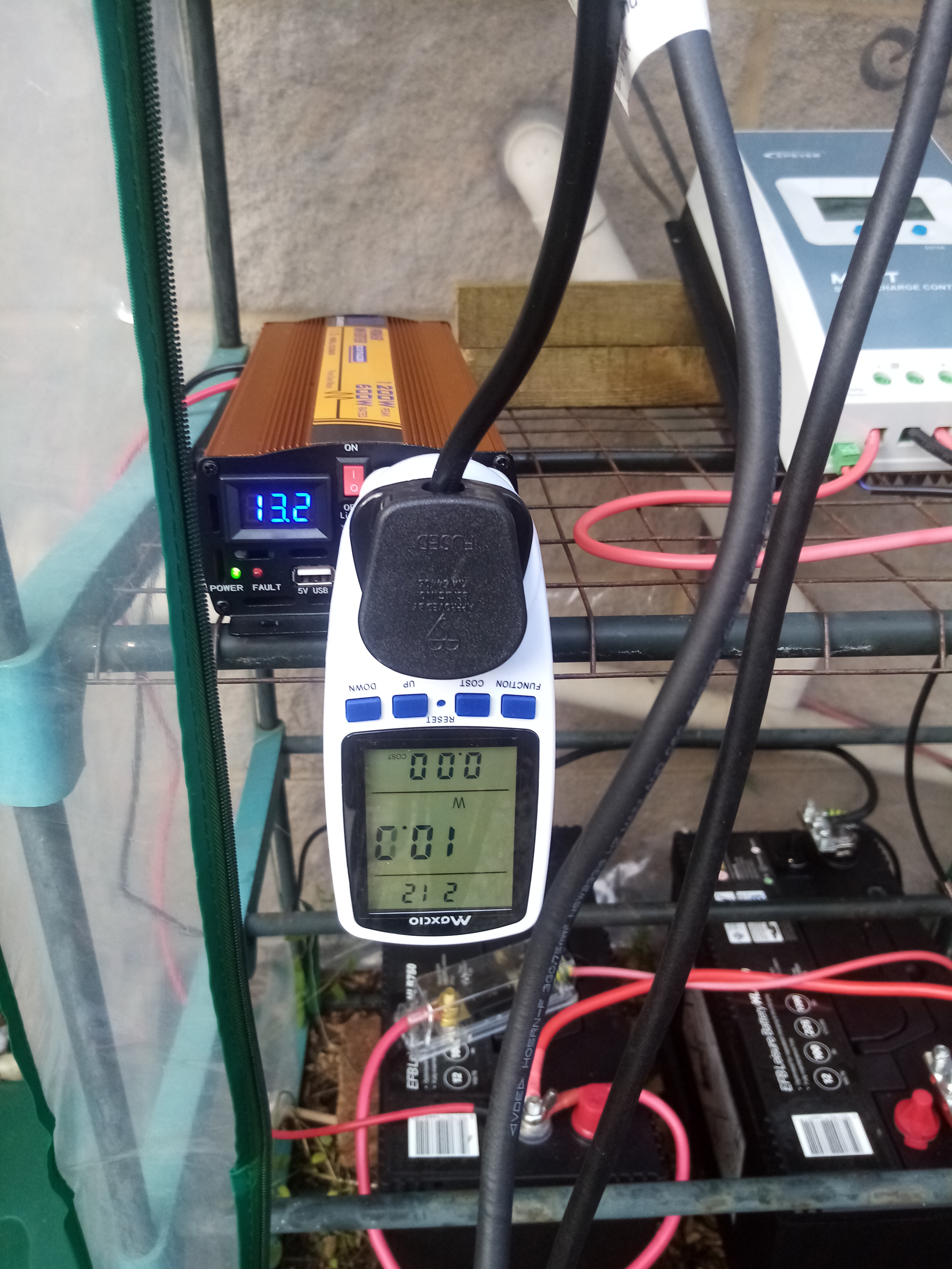
Little sequence of checking the pond, followed by switching the pumps on, one at a time and monitoring the usage. Here's the 10watt usage from pump number one reading quite nicely:


Because I cannot "let it lie" (a 1990s comedic joke for those that are old enough and obscure enough to remember), I had to then move onto the next phase of the phase 3, shall I say, "plan"?
The digital timers arrived! So simple to setup, even I could work it out - even though I did actually read the instructions to make sure I had done it right, as they were so simple:


Now....the phase after the last phase...that will be the last part of this current phase!
Automatic Transfer Switching (ATS) - this is basically a reverse UPS (uninterruptible power supply), whereas most things, like computer servers have mains 240v power and if that is interrupted / cut-off they then switch over to batteries for 10mins and if longer than that they then shut the system down, we want to do the reverse of that.
We want to be running solar -> batteries for as long as we can. However, if there have been 3-4days of no sun, little UV light and basically a bit grotty, but we've still been draining the batteries by using the pumps etc... then the batteries will hit a point where the voltage within them will get dangerously low.
What I mean by dangerously low, is what happened before, they get down into the 11.8volts or even worse 10volts that happened on the first battery and basically as they are NOT lithium, they are dead. Kaput. F***d. You get the picture. At around £145 each, that's no joke. So what do you do?
Well, you fit this ATS device. Again, very simple to setup - even an idiot like me could do it in minutes. Basically, you set an LV (low voltage) value and an HV (high voltage) value, at what point do you want the ATS kit to kick-in at when the voltage gets to low in the batteries and then once it switches over to the mains power to re-charge the batteries, when do you want it to then switch back to running from the batteries. Simple.
One thing that did catch me out a little whilst "testing" this was the number you put in isn't the "trigger" value, it has to go to the next value. For instance, I put in LV of 12.6volts, this doesn't mean it will kick-in at 12.6v, it means it will kick-in at 12.5v. Just something to be aware of.

As mentioned, the "output" connects to the actual power inverter device and the left-hand input is for connecting to the mains power - who needs an earth?


This is all just for current testing (did you see what I did there? ;-) )

There we have it - I set up a simulated testing environment where I could force the ATS system to trigger and switch from the Battery power to the Mains power - on the LCD screen, bottom right, notice the input arrow is empty and the Mains power input arrow is full. I had this setup to trigger at 13.1v and 13.3v so I stood there like a lemon drinking a cup of tea for 30 minutes watching / listening to it flipping between one power source and the other. Why so long and so frequent? Well, being someone who does still write computer software code, I like to test that code - also I never trust version 0.1 of the code, it usually doesn't have any exception handling and is just "happy-path" coding, so that's what I wanted to test here... my electronic gadgetery coding. Also, as we're playing with 240volts now, I wanted to make sure nothing caught light, burnt out or tripped the house fusebox! All seemed to be good. BTW - I left this running over night and tested again the next day, just to be sure, it does seem like it genuinely is all good.


As I say, it is pretty much complete for this phase, I now just have to work out how to "migrate" this setup to be within a professional waterproof container the other side of the kitchen window.


...and there was me thinking this phase was finished with - hahahahhaaa... until next time.
UPDATE:
okay, so I was away from home for 3-weeks and it seems like the solar setup did it's job, the fish are still alive and well and nothing burnt down....however......
whilst away, I started thinking about the diagram above... the "loop" on the bottom right between the battery and the inverter was causing me mental anguish. If you look at the images above, I connected the 12v battery cables directly into the right-hand side of the ATS and the output 2 cables connected to the back of the inverter. That made logical sense as that is the "load", ie. the items will be plugged into it.
Anyway, short story - that is ALL wrong! It was baffling me that when the mains power (2 cables on the left-hand side) got tripped then all the power would cut-off until the batteries were charged again by the solar panels. I read and r-read information and I watched a few YouTube videos that showed that when other people's ATS switched over to the mains everything would carry on okay...with no off power. Annoyingly, none of the videos actually showed the setups properly. Until I found this YouTube video:
Rewind, re-watch, rewind, re-watch, scratch head... stand in front of the setup in the garden, scratch head and then the penny dropped!
Ah!!!!! So, the input power FROM the inverter should be 240v and not 12v from the batteries?! So...instead of connecting the 12v battery power, I needed to connect the inverter to the batteries and make a plug for the 240v output and connect THAT as the 2 cables on the right-hand side! That now makes sense!
The output 2 cables in the middle will be directly to the 4-socket extension cable, ie. what the 3xpond pumps are connected to.
The mains input is absolutely fine as-is, no issues with that.
Now, this setup makes a lot more sense and looking at the diagrams for the ATS, it kind of makes sense now - however the A4 page instructions that I was referring to, totally useless.
However, I believe I either have a faulty ATS unit or when I was setting it up (wrong) I broke something, as when the mains power kicks in all power goes off - this should not happen, it should just switch over and carry on seamlessly.
I've ordered another ATS device as I'm way out of the return date - when that arrives, I'll set it up as I have it now and it should then start working as it should, which would mean the pumps will run 24/7, just using solar power during the day and mains power during the night.... that is until I get more batteries for more storage so the batteries can last all night and all day.
When it's setup and working, I'll drop a photo of it here.
UPDATE : UPDATE : UPDATE : UPDATE : UPDATE : UPDATE : UPDATE
Ha...so after ordering a new ATS device and swapping over the cables, switching everything on and sitting and waiting... the EXACT same thing happened! "NOoooooooo!" could be heard echoing around the Westbury white-horse hills. Baffled, I did what I do best. I troubleshooted.
Basically, I doubted anything that "I" had done, that's always the first assumption of failure - I've done something dumb. The second assumption is that something is faulty and the third is something is not connected up correctly.
I was pretty sure that I was ruled out of the equation here. I had a new ATS device, so that ruled out the second assumption, so that just left the third.
With this in mind, I set about putting the original ATS device back into place - if I did wire something up wrong, then at least I wouldn't be destroying a new ATS device.
I was a little baffled as when the ATS switched over from Solar / Battery power to the home power it then cut-off the power. I plugged some USB sparkly lights into the extension lead that I was using, there are 2 slots for USB usage on the end of the extension lead - this proved to be much cause of red-herring-ness later on! I connected up a single extension cable as a go-between the extension cable that was powering the pumps and I plugged the Watt usage monitor in between. My theory was that I could monitor the pull / load being pushed/requested by the pond pumps connected to the extension lead.
This proved insightful. I could see 1-2Watts being used, turns out for the USB lights - now, this value showed all the time. I expected to see 30watts for the pond pumps, plus the lights, so about 32watts. I was a bit baffled, how were the USB lights working from the extension lead, but the pond pumps were not? The USB extension lead allows for 5v and 2A and they were being powered - this confused me for a bit... and then I thought, hang on - let me totally unplug the mains power from the ATS device and let it switch over. I did this and the same behaviour happened. So, with NO power it behaved the same as me plugging it in.. I then took the plug that was connected to the ATS for the mains power and took the 13amp fuse out and replaced it. Plugged it back in and voila! it switched on and worked straight away. Ah! it was so simple, it was just a blown fuse that must have happened when I was faffing about disconnecting and reconnecting between the ATS devices? anyway, it was raining whilst I was doing all of this and mostly getting dark (hence the USB LED lights!) so I left it all running, the pond pumps were doing their thing and I was now happy that the mains power switch over was working.
However, the next day...I then noticed the USB LED lights were on, but the pond pumps were off... I looked at the front of the ATS device and the big arrow <= was pointing as feed input from the solar panels / batteries. This should have been working as that IS what has been working for the past month or so totally fine. I now have the total opposite problem to what I had before! AAAARRRGGHHH!
I did the first obvious thing and unplugged the inverter plug and switched out the fuse - no difference.
Hmmmm.... now I was a bit baffled. What was different? Had I fried something inside the ATS device that meant it was working in an unstable fashion? I then looked at the setup again.... that was when I then received my power socket tester device from good old Amazon.

My theory was that for some reason not enough power was getting passed through the ATS device to the output and that is why the pond pumps were not powering up - it didn't make sense as it worked one side but not the other and now that had switched. So I thought I would use this clever device to show me exactly the VOLTS that were going through the cables, that might give me more data.
Oh and it did! It turns out that at some point during the above, for some reason I had switched back to using the "old inverter" or "inveater" as it says on it...now, this states it is 1500w and I have had it the longest, whereas the gold one that I got with the solar panels from EcoWorthy is 600w and for some reason I had swapped them over.

I plugged in the socket tester and it showed that the power voltage from the batteries was fluctuating from 210-219volts.... hmmmmm.... I swapped inverters and plugged everything back in (without touching the ATS device) and BOOM! it worked straight away, pumps were pumping using solar panels / batteries. I connected the tester and it showed 233-240volts... I was actually right previously, it was due to not enough grunt coming out of the inverter to power the extension lead. The USB LED lights were always working probably due to the low voltage/amps, something to ponder for a later date.
So, now I FINALLY have a setup that is working as it should and I stood there and watched it switch multiple times from battery power to mains power <= to => and there is absolutely no drop in power the pond pumps keep on pumping and doing their job. Lesson learnt: pay for the good stuff / use the good stuff. cheap stuff just gives you problems.
FINALLY I have a setup / system that does what I wanted it to do originally! What a learning curve!

Ignore the mess / mass of cabling, this is in "debug mode", but I thought I would capture it as the final end result! I do now have a spare ATS device ($150) that will cost me far too much to return back to China (yes, I ended up buying one direct from MOES in China and having it shipped as there were none available in the UK) - maybe I will keep it along with the other two 2000watt inverters that I can use for the GREENHOUSE 2023 project I have lined up :-) At least now, I have a template pattern for getting it right first time and a decent trouble-shooting guide!
Phew! here's an "architectural diagram" for when I need to repeat it again:

I think I mistakenly added a 50amp fuse between the MPPT controller and the battery +ve input, I think the logic was to put some throttle there, but I'm pretty sure that the MPPT controller itself does thaat, so that might be overkill / redundant. Where I should have a fuse is for the inverter - that has 2 built in 40amp fuses (car blade style) connected to the back, so that is probably okay too. The 3-prong electical plugs all have house 13amp fuses within, so if anything goes above that threshold from mains input and the inverter input, they'll go "pop" and save anything dodgy from happening.... the output, well, the output is not fused at all. At the moment, it does have a singl extension lead connected to it and the 4-way extension lead is connected to that, which is not ideal, but it allows me to unplug it / remove it and also allows me to move the watss/monitor in the middle fror troubleshooting, so I'll keep it in place for now. Apart from that, I can confirm that it has been sunny / cloudy day today and it has been operating for the past 24hours exactly as designed. sweet.
AS STATED ELSEWHERE : this information is purely for myself, I'm NOT a qualified electrician, I'm a hobbyist, if I've done something wrong, then let me know. If you decide to follow this, then you do so at your own risk with absolutely no liability from myself. I had to figure this stuff out and learn, so should you - I may have helped you understand a few troubleshooting things with this information - it is NOT a guide on how to setup solar and if you burn your house down, that was all on you. If you don't know what you are doing, get in a professional, house insurance tends not to pay out if they hear you've hacked something dodgy together and that burnt your house down. keep that in mind.
Next steps: setup the USB / RS485 cable to allow me to monitor the MPPT controller from a raspberry pi, to keep an eye on the solar charging cycles and to determine if / when I trash my two leisure batteries. Then setup a web cam to monitor the setup and add sensors for fire / smoke / gas to keep me alert and potentially rig up a "put the damn fire out" system, just incase it's ever needed.


Comments
Post a Comment