PICO C-code - (part 1) ....and maybe a bit of VGA
Right, I've done enough of the MicroPython stuff now.... let's get back into my comfort zone.... let's go back to the 1990s and write some C code 🤓

Okay, C code isn't specific to the 1990s, but it is when I was first introduced to it....(actually it may have been 1989, but who's nit-picking) and I've been using it on the Arduino for a few decades now. So it makes sense to now remove the training wheels with the PICO and get back to the lower-level. As I'm wanting to do stuff with the VGA screen output, it makes sense to go down a layer (I'm keeping above the ASM waterline for now!)
The image above actually comes from THIS webpage, however, I didn't follow those instructions, I did however learn something new...scrolling down the article, the nice chap let's us know that GPIO Pin 30 is a RUN pin and if you flip it then it does a hard-reset - this saves you having to unplug the USB cable and plug it back in every time you want to reset - that's an awesome piece of info.

What did "I" do... well... I did my usual and didn't read any instructions and thought that a combination of what I'd already setup for the MCUME that builds fine was going to be okay for me... it wasn't. Also, of course I haven't downloaded the pico-examples and attempted to use those either. I didn't get to where I am today by following things, you know... I like to learn the "hard way" (okay the stupid way), I just want to make a simple HelloWorld from scratch and that makes sure that the config is setup correctly and I'm not tied into a pico-examples folder where only their setup works and then I have to spend ages figuring out how to make it work in a different folder.
With that in mind..."what did I do"?
Well, I'm running UBuntu 22.04 (of course), so a quick search led me to here:
https://lindevs.com/set-up-raspberry-pi-pico-sdk-on-ubuntu/
Basically follow the same steps, as-is.
The PICO-SDK is downloaded & saved into /opt/pico-sdk
That is actually more useful than what I'd done previously where it was embedded somewhere under a complex /Downloads/ spider path.
The only change I had to make was to the CMakeLists.txt file. The article said to use:
project(myapp C CXX ASM)
However, when running make, I would get an error at the last step in the build creation step.

I found that simply removing it:
project(myapp C CXX)


That then copies the myapp.uf2 file onto the PICO.... and you'll hear it go be-boop again. Is anything happening though?

OKAY - that is pretty friggin' awesome. I have some C code, written, compiled and deployed as a uf2 file that is auto-executing on the PICO device at the lowest layer/level.
What is so special? Well....previously I had to download the Pimoroni uf2 file that they had built/created from their own C code and then the MicroPython code would then "use" that code via library imports etc..etc... this does mean that the MicroPython code is running slower as it is basically running as an Interpreted language, a bit like running BASIC back in the 1980s.
It's great to get you up & running and to test / prototype what you want to achieve, once done, then it's time to move it into the lower-layer where you can "do it for real". Again, just like back in the day when you went from writing code in BASIC and then moved into writing it in ASSEMBLER...
..or was that just me?....hello?.... errr.... ah, found this guy who agrees with me!
He's writing an Atari 800XL (coincidence that I just happen to "find" this?) game in BASIC and then porting it over to ASSEMBLER - the speed difference is dramatic, but so is the length of the ASM code!
Didn't the title mention something about VGA?
yes. yes I did.
So, now it is time to put this down:
https://datasheets.raspberrypi.com/pico/raspberry-pi-pico-c-sdk.pdf

and take a little look at this one instead:
https://datasheets.raspberrypi.com/rp2040/hardware-design-with-rp2040.pdf

Well... that's seems pretty simple:

Now, that is interesting... Red, Green and Blue just have a PIN each, then VSync and HSync have a PIN each and the rest are basically GND. Wow, I thought VGA was more complex than that. Okay, so on the PICO side of things, you end up having to use a LOT of pins for each of the R, G and B

I did read that getting too picky with the resistor values is something you can obsess over, or just look at it as you start with 500 and then just double each value as you go upwards!
I did watch this YouTube video, but decided that was far too much grief.
If you really want to get into the nitty-gritty details, even down to "how" the pixels are output to the screen, not using framebuffer - then this guy is you man to watch:
So, I did the usual and lined the pockets of Pimoroni (very well earnt ££)
https://shop.pimoroni.com/products/pimoroni-pico-vga-demo-base?variant=32369520672851

If you turn the image, rotate left 90-degrees, all those PINS on the left of the PICO are used for the RGB and the H/V-Sync are the GPIO 14/15.
Here is the reverse image that shows how the PINs are used:

Actually, if I can do a bit of jiggery-pokery I reckon I can get the MCUME working on this thing... it also has 3-buttons (see top picture) and all I need is 3-buttons for the "keyboard".. hmmm....
Interesting that they don't mention the 3-buttons on the layout either:

okay, it's at this point, that I just might need to go and get the EXAMPLES and see how they work with the VGA screen output.
https://github.com/raspberrypi/pico-playground
To quote this page:
"This repo is similar to pico-examples but utilizing additional libraries from pico-extras "
a
The really cool thing about this Pico demo board is that it has the [RUN] button installed - so like mentioned above, pressing it down and holding the [BOOTSEL] button does the hard-reset without having to remove the USB cable.
Okay, I downloaded the pico-examples github repo and then did the following:
cd pico-examples
mkdir build
cd build
cmake ..
make
This then walked through all of the folders inside the pico-examples and made the uf2 outputs:

If I step into "blink" folder and then copy the file to the PICO:

I now have a blinking flashing light on the PICO. sweet. okay, that proves that the code compiles and builds okay and is cross-compiling okay for execution on the PICO.
Right....onto the pico-playground and the VGA stuff(s).
well, that's no fun:

tut!tut! manually setting that value didn't do the job. So, time for a quick EDIT:

followed by a quick:
and we're back in business. Obviously I had to git clone the pico-extras first...
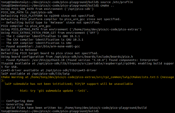
That warning is fine as I'm using a non-WiFi PICO. looking better.
after a very quick cup of tea and a make later....

Looks like all the uf2 files were made successfully.
Let's pick one at "random" and upload it and see what it does..............
here's the code that is being executed:
https://github.com/raspberrypi/pico-playground/blob/master/scanvideo/sprite_demo/sprite_demo.c
as you can see, it's pretty clear / awesome and is indeed outputting VGA from the PICO:
OKAY - TO BE CLEAR - my phone camera is CRAP! It was having a bit of a fit trying to do the [face recognition] thing by putting blue boxes around every face and still trying to take a photo, I think it got a little overloaded doing two things at once... it is 3years old, bless it! I'll make a video later.


of course, I have to change the image, just to prove that it works when I re-compile 🤓
....once I figure out how to convert an image of me in my cowboy hat into byte values....
and, now to also try out some of the other examples...before I move onto my own experiments... well, it is New Years eve... I wasn't planning on doing anything else this evening, apart from maybe watching an old James Bond movie, followed by The Goonies, followed by Indiana Jones (or whatever they have chosen to put on TV)... and well, then it'll be time for some geeky C coding, won't it.... roll on 2023
UPDATE :
okay, because I couldn't let it go.. and it was only about 4pm.... I went back to the MCUME code / configuration.
Now, just tweaking the config to now use VGA/ILI9341 screen as output (*come back to this later)
//#define SWAP_ALT_DEL 1
#define USE_VGA 1
#define ILI9341 1
#undef ST7789 1
#define LOHRES 1
#define FLIP_SCREEN 1
#define INVX 1
#define HAS_SND 1
#endif
and a little extra tweak:
pico_enable_stdio_usb(mcume 0)
Although I cannot figure out (yet) where this is outputting to?
I had ass-u-me-d that I could use the minicom and listen on /dev/ttyACM0, but that doesn't seem to appear at all... hmmmm....
Then a rebuild and generation of a new .uf2 file... drop it into place...and nothing.... then it dawned on me that the code is attempting to read from the SD-Card and I've not configured that at all for the PICO DEMO BASE thingy.... well, that will be simple enough.....
Oh dear. no it won't! All it says is that some PINS are used for DAT0/1/2/3 - that tells me nothing.
Off I go digging... from the hardware PDF linked to earlier, I get:

Then I find this image in relation to ARDUINO and SD-Card usage:

of course it is back to front! anyway, that then gave me the info I need to know / mixed with the image above.
Now to change the iopins.h file:
#define TFT_SPIREG spi0
#define TFT_SPIDREQ DREQ_SPI0_TX
#define TFT_DC 15 //28
#define TFT_MOSI 19 //15
#define TFT_SCLK 18 //14
#define TFT_MISO 16 //12
#ifdef PICOMPUTER
#ifdef PICOMPUTERMAX
#define TFT_RST 14 //255 // 255 for ILI/ST if connected to 3.3V
#define TFT_CS 17 //13 // 255 for LORES ST7789 (NO CS)
#define TFT_BACKLIGHT 255//20
#else
#define TFT_RST 14 //255 // 255 for ILI/ST if connected to 3.3V
#define TFT_CS 17 //13 // 255 for LORES ST7789 (NO CS)
#define TFT_BACKLIGHT 255//20
#endif
#else
// MCUME_REV2 (ILI)
#define TFT_RST 21
#define TFT_CS 17
#define TFT_BACKLIGHT 255 // hardwired to 3.3v
#endif
// SD (see SPI0 in code!!!) - totally not sure about these
#define SD_SPIREG spi1
#define SD_SCLK 5 //10 //14
#define SD_DETECT 22 // 22
//21? - not used
#define SD_MOSI 18 //
#define SD_MISO 19 //
#define SD_CS 22 //
I also tweaked these two values that were above these settings, as the VSYNC and HSYNC are around the other way on this board:
//#define VGA_VSYNC 15
#define VGA_SYNCBASE 15
#define VGA_VSYNC 14
Followed by yet another rebuild and deploy....
OOOOO MMMMMM GGGGGG - I got SOMETHING?!?! It might not be anything useful, but I got something?!?!!

The onboard LED flashes 30-times (yes, I sat, watched and counted) as is it is attempting to "do something" or wait for something to be pressed... so this is looking positive, I hope....

I added in some debugging (correctly this time)

...and I can now see what the LED flashing is all about! It seems like it cannot read the SD-Card - okay, so somehow my config is not correct, well, there are only so many permutations! I best get switching them around....
But, ignoring the VGA screen output being garbage... it is at least showing some form of progress?!?!
Also, I can now see which piece of code is failing... "let's going further into this rabbit hole, Alice"
I've read that someone got DOOM running on this setup, with SD-Card, Sound AND a keyboard - I think the keyboard is the bit I need.... right...internet... where is this information! Okay, I found this info and turns out it was an ex-IBMer from Warwick that made that possible. geeks, the lots of them. It also turns out that it's not using a method that I'm doing here, so cannot learn from it. oh well.


Comments
Post a Comment